


This weekend I started on my newest project using a RaspberryPI. It will involve my garage door and a notification system to notify when the door is open. I have seen many impressive systems on the Internet that already do this using different setups usually with relays. With my new knowledge of transistor circuits, I have decided that this is how I am going to implement my solution.
The background on this is that I often find our garage door open. Often a door is left open by accident, or during the winter one of the doors bind and re-open as my wife or I unknowingly drive away. So this system will have to have a way to view the current position of the doors as well as be able to control their state.
I did pick up a PI-Face last week which is really cool, and it ties to the GPIO pins and exposes a set of relays and other control elements. I could use this for the project but decided that I would rather save that for when I get back to my robot (which is turning into a long drawn out project 😉 too many cool technology things these last couple of years – it’s amazing…)
Tonight I took the controller box apart to see if I could reverse engineer the circuitry that controls the garage door. Not much to it in fact: 3 switches, a couple of capacitors and one resistor (plus a power LED). The circuit controls the door, a light and also has a lock function which (I found out today) effectively locks out any remote control units.
Initially I decided that I wanted to support the opening of the door, and also the light. I am still undecided if I will support the lockout function, but likely I will include that as well. So step one was to trace the electronics to see if I could reproduce the functionality on a breadboard. Yes, I could have just jumper-ed into the existing board, but I thought that this would be a far better learning tool by reverse engineering and implementing my own switching circuit.

Garage control front view – shows components
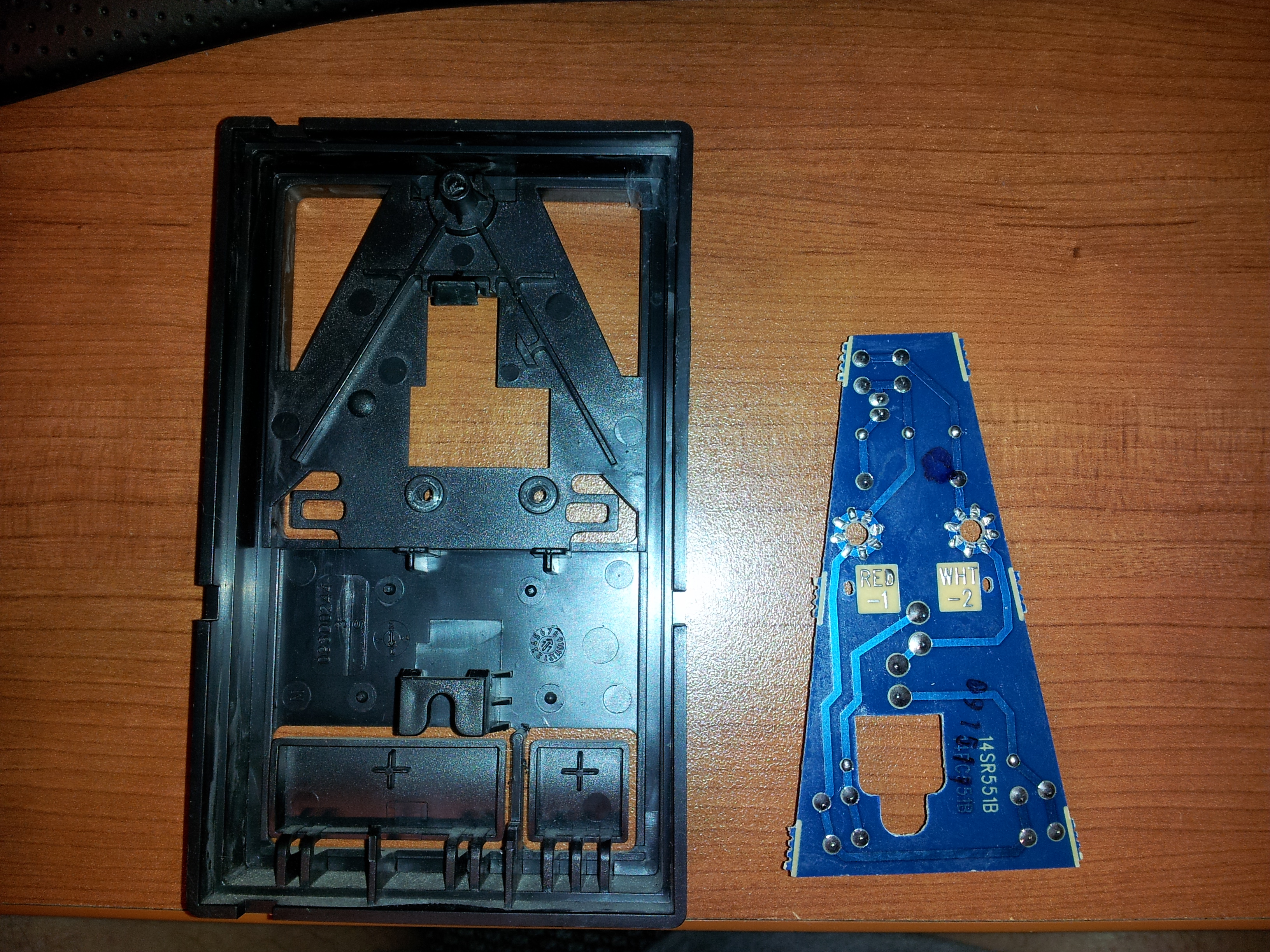
Garage control back view – shows traces
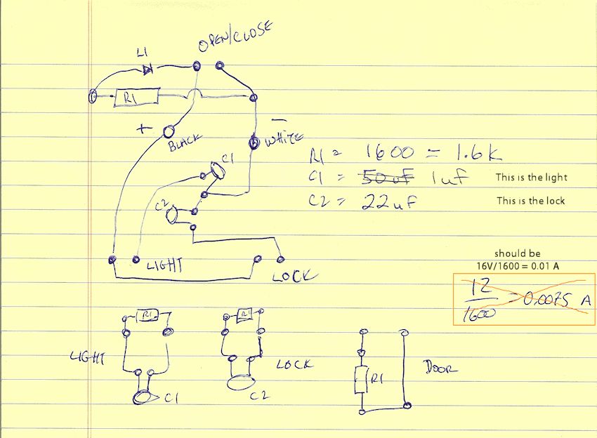
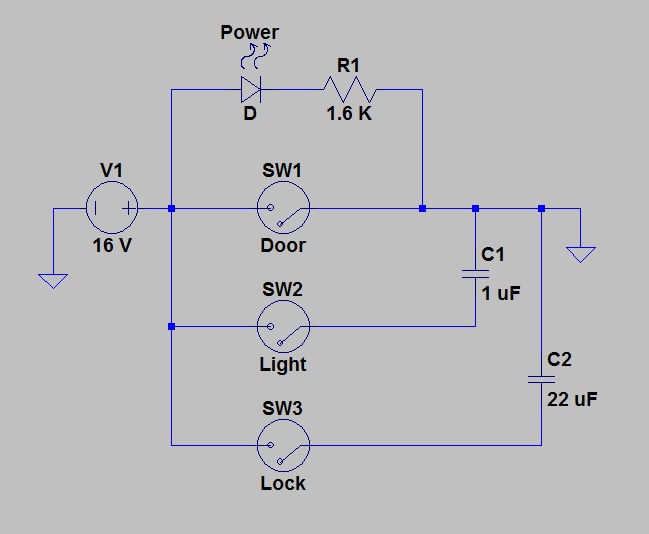
My interpretation of the circuit
I found that the voltage on the line was 16V, so will definitely have to be careful working with this around the PI. With this kind of voltage, I might be able to power the PI as well so my potential circuit gets more interesting (with voltage regulation; which I will have to learn more about). I should also mention that I have two garage doors with the same control box, so the final circuit will need to support 2 doors, 2 lights, possibly 2 lock options and also a regulator to power the PI.
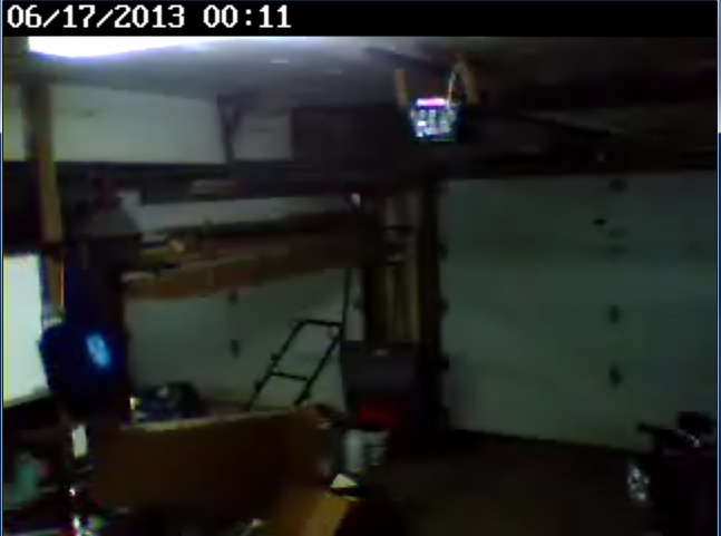
WIFI camera image using Windows Media Player

can see one of the doors is closed
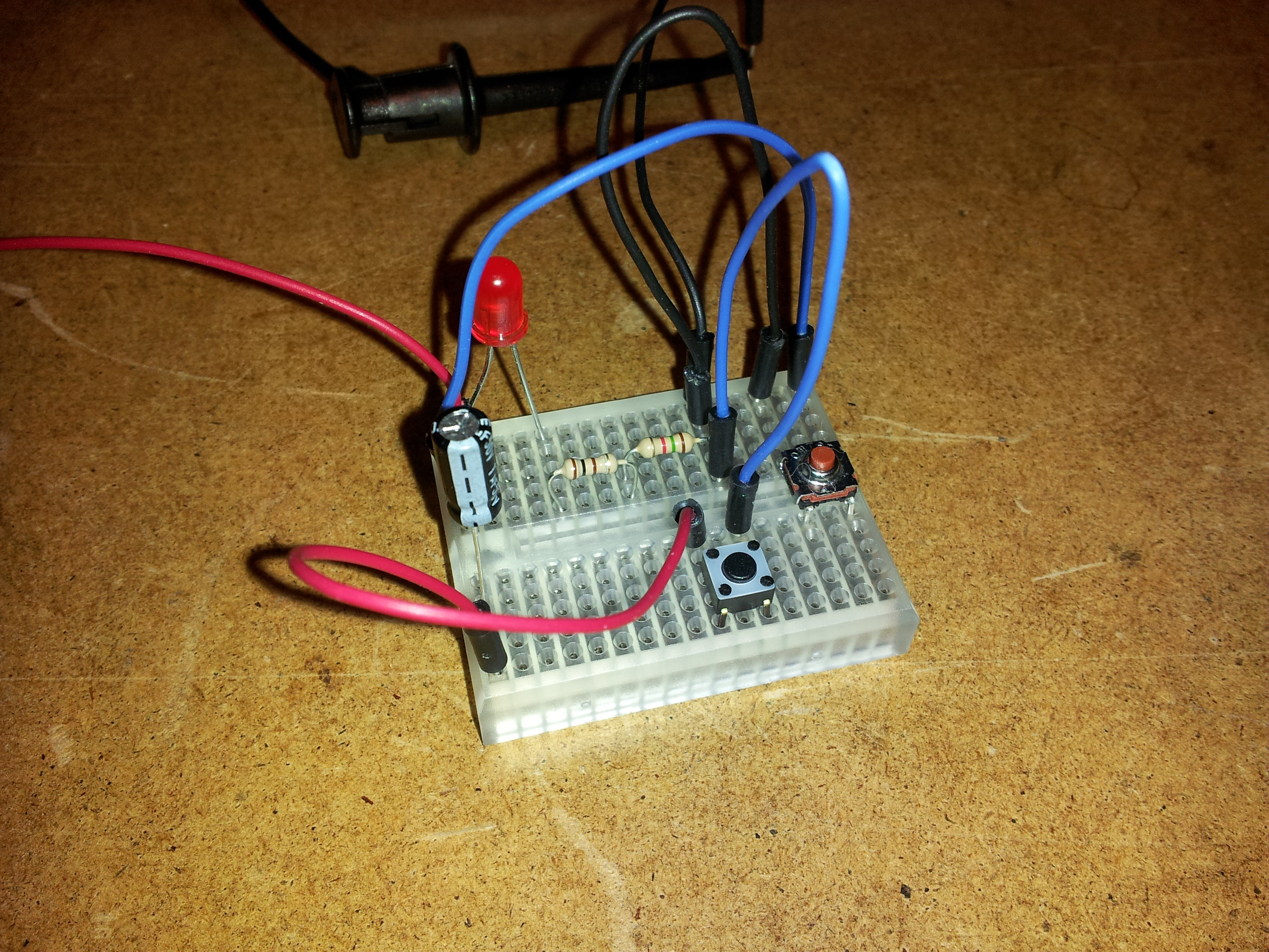
Circuit copied to breadboard (had to use 2 resistors for 1.6K)
Next step is to move this to a GPIO controlled circuit that will be linked with the PI.