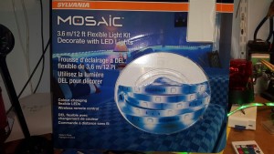
This Fathers Day I was wandering around Costco with my family when I saw what would become my next project. It’s funny where and when someone can get inspiration. The thing that caught my eye with the LED display was the fancy multi-colour remote that was displayed on the front of the packaging.
When I saw the package I couldn’t help to think of all the amazing things that could be created with a flexible string of LED lights. Of course my son who was with me only helped to fuel the fire and my daughter shortly after, started making requests about colours and where the lights could be located. Certainly all reasonable ideas, but I had my own plans which began with the dis-assembly of the controller and LEDs.
So I bought the LED set for about $30 and couldn’t wait to get home to take it apart and rebuild it to create a phenomenal light show. The set came with a remote control, and 6 two foot lengths of LEDs (12 feet total). From the packing it was obvious that the LEDs could display all sorts of different colours. The way that the system achieves this is with a standard RGB (Red/Green/Blue) colour code which represents the brightness of the three coloured LEDs within each “light”. The way the lights are wired, the controller can only make the string one colour or have it rotate through a set of colours, but at any point in time the whole string can only be one colour. Still a great buy in my mind for $30.
Once I arrived home I couldn’t wait to open the packaging and start the process of ripping everything down to see what pieces I might be able to use for any future project. Upon opening the controller, I wasn’t terribly surprised to see a basic transistor circuit. One transistor controlling each of the individual RGB levels to render the resulting colour. Within the circuitry I also found a memory chip and a chip that I wasn’t able to find any details about. I surmise the memory chip was for the storage of last used settings etc. The “unknown” chip I suspect was the controller for the IR LED that was the receiving end of the remote.
The transformer was a standard 12V 2A wall wart and I tapped the lines to see what I could get as far as readings on the power levels. There was a 140Hz signal on the line which controlled the LED signalling so I figured it was a digital PWM (Pulse Width Modulation) that was used to control the LEDs. With PWM, the LEDs are basically flickered off and on very quickly in order to avoid burning them out with constant current. Since the human eye does not see the flicker above (I believe) 50Hz this all made sense.
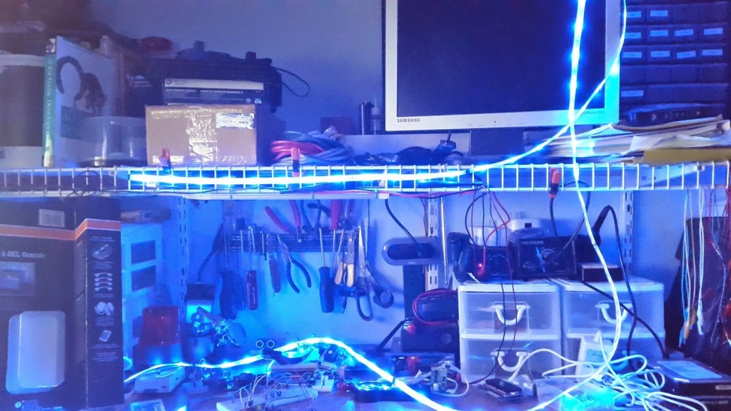
I had done some research on PWM a while back while playing with the Arduino. As a result, I figured I could do something with my Arduino, and some simple transistors. So by creating a simple transistor circuit and connecting to my bench supply for the 12V I was able to light he LEDs and after a bit of fiddling I was able to create all the colours that the remote was able to create.
The results can be seen here:
The RGB values are tracked in an array of integer triplets. The value for RGB (and Arduiono PWM) is a range of 0-255. Within the arry you can see values that represent colours, such as:
  {255,  0,  0},  // red
  {  0,255,  0},  // greeen
  {  0,  0,255},  // blue
So the basic colours red, green, and blue are represented as listed.
I created a simple blink routine that simply blinked the current colour by showing the colour, turning all colour off (all zeroes), and then repeating this sequence a number of times.
My daughter liked the built in remote function that faded one colour to another so I thought that would be a good one to reproduce as well. Since the colour is quite linear in each colour component the math was not difficult to achieve this.
Basically if we were on red (255) and wanted to go to black (0) then based on the number of steps, the colour would decrease. I chose 100 steps, so the colour was adjusted (in this case) by 2.55 with each iteration. RGB is integer based, so I did all math first with floating point values then cast to integer.
My Arduino sketch (code) is attached.
LED_testing.ino
